问天M9飞控Readme
ZeroOneM9 Flight Controller
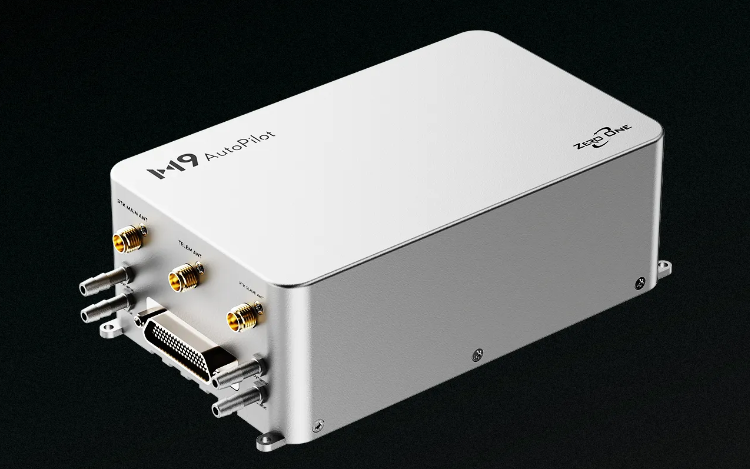
The ZeroOne M9 is a flight controller manufactured by ZeroOne, which is based on the open-source FMU v6X architecture and Pixhawk Autopilot Bus open source specifications.
Features
- SCH16T&ADIS16507 powerful IMU inside
- Integrated anti-jamming dual-antenna RTK
- Integrated 439.9km/h dual-redundancy airspeed meter,Meet the requirements for measuring airspeed from low-speed to subsonic flight
- Industrial-grade aviation plug,reliable connection
- Built-in high-performance dual-fan active cooling
Processors & Sensors:
-
FMU Processor:STM32H753IIK6
32 Bit Arm® Cortex®-M7, 480MHz, 2MB flash, 1MB RAM -
IO Processor:STM32F103
32 Bit Arm® Cortex®-M3, 72MHz, 64KB SRAM -
On-board Sensors
-
IMU:
Internal Vibration Isolation for IMUs
IMU constant temperature heating(1 W heating power).
With Triple Synced IMUs, BalancedGyro technology, low noise and more shock-resistant:
IMU1-SCH16T(With vibration isolation)
IMU2-ADIS16507(With vibration isolation)
IMU3-IIM42653(Hard Mounted) -
barometer:Two ICP20100
-
Magnetometer:Builtin RM3100 magnetometer
-
RTK:
-
telemetry
Integrated long range telemetry radio Microhard P900 -
airspeed sensor
two airspeed sensors,Maximum measured airspeed 439.9km/h
The first airspeed sensor communicates with the flight control through I2C(bus2).
The second airspeed sensor communicates with the flight control through CAN1.
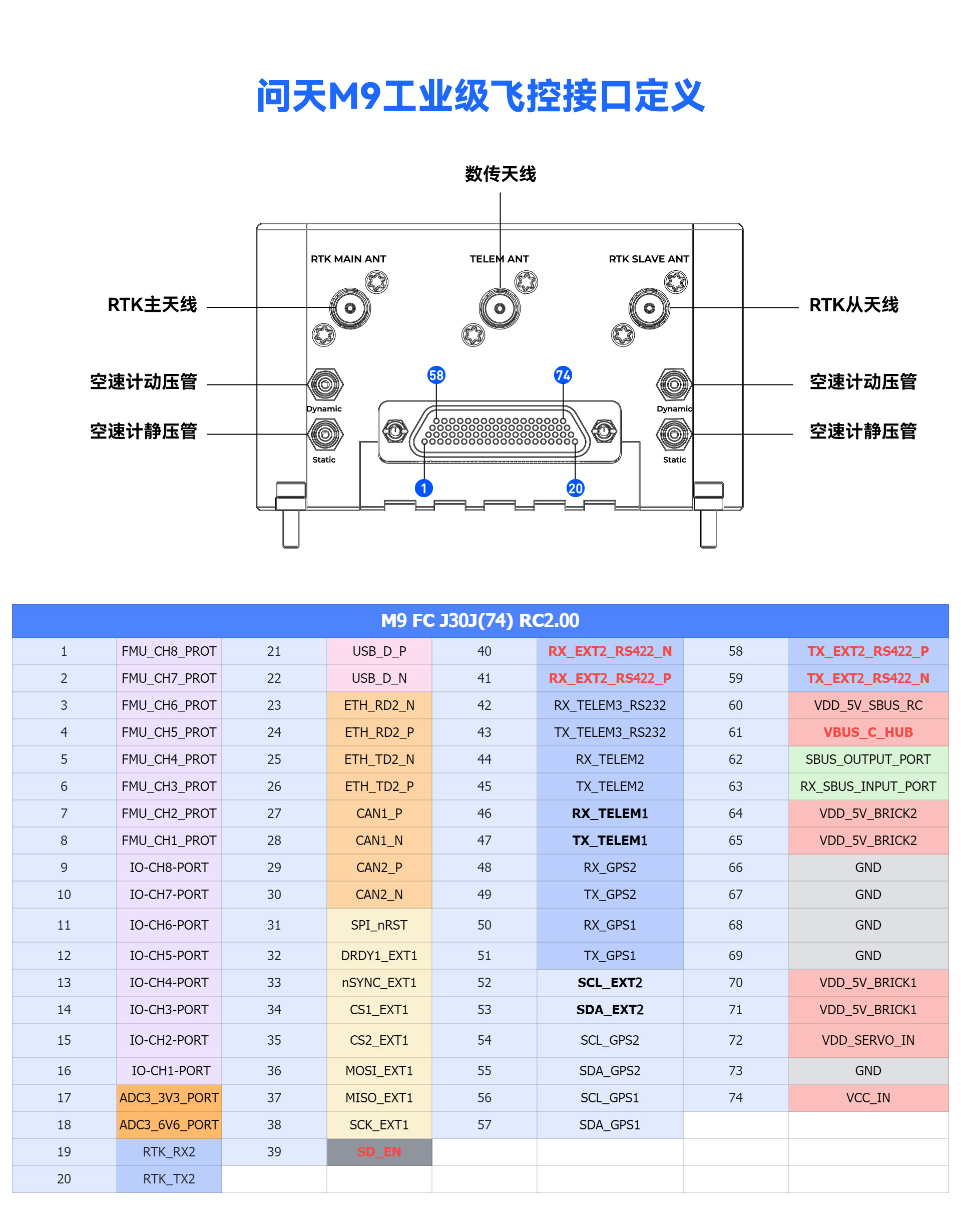
PinoutS
J30J Interface Definition
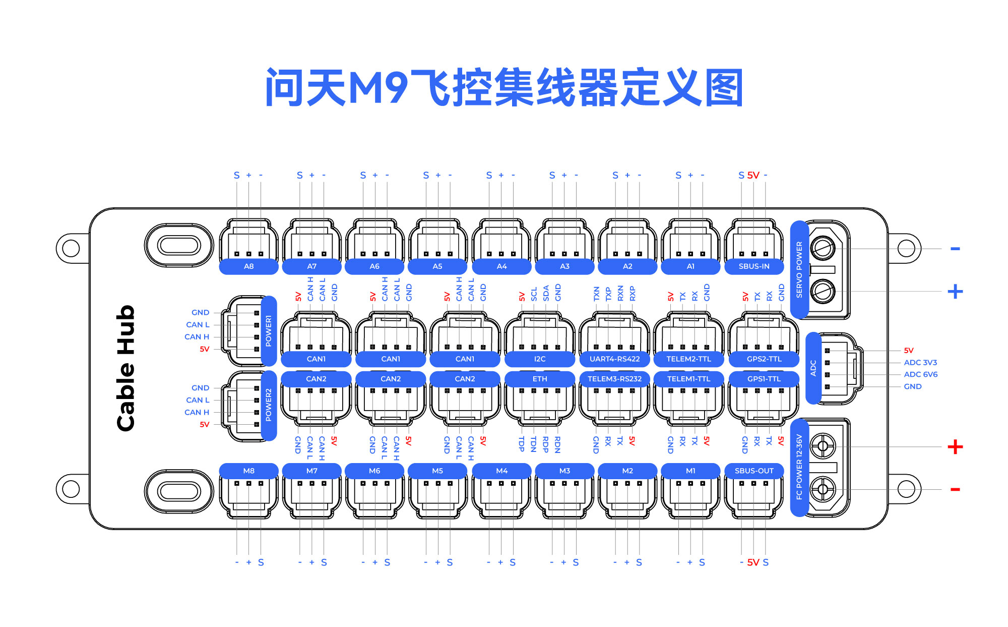
Extended Hub Interface Definition
UART Mapping
The UARTs are marked Rn and Tn in the above pinouts. The Rn pin is the receive pin for UARTn. The Tn pin is the transmit pin for UARTn.
| Name | Function | MCU PINS | DMA |
|---|---|---|---|
| SERIAL0 | OTG1 | USB | |
| SERIAL1 | Telem1 | UART7 | DMA Enabled |
| SERIAL2 | Telem2 | UART5 | DMA Enabled |
| SERIAL3 | GPS1 | USART1 | DMA Enabled |
| SERIAL4 | GPS1 | UART8 | DMA Enabled |
| SERIAL5 | Telem3 | USART2 | DMA Enabled |
| SERIAL6 | UART4 | UART4 | DMA Enabled |
| SERIAL7 | DEBUG | USART3 | DMA Enabled |
| SERIAL8 | OTG-SLCAN | USB |
RC Input
The remote control signal should be connected to the SBUS RC IN port or DSM/PPM RC Port.It will support ALL unidirectional RC protocols.
PWM Output
The 问天M9 flight controller supports up to 16 PWM outputs.
First first 8 outputs (labelled 1 to 8) are controlled by a dedicated STM32F103 IO controller. These 8 outputs support all PWM output formats, but not DShot.
The remaining 8 outputs (labelled 9 to 16) are the "auxiliary" outputs. These are directly attached to the STM32H753 FMU controller .
All 16 outputs support normal PWM output formats. All FMU outputs, except 15 and 16, also support DShot.
The 8 IO PWM outputs are in 4 groups:
- Outputs 1 and 2 in group1
- Outputs 3 and 4 in group2
- Outputs 5, 6, 7 and 8 in group3
The 8 FMU PWM outputs are in 4 groups:
- Outputs 1, 2, 3 and 4 in group1
- Outputs 5 and 6 in group2
- Outputs 7 and 8 in group3
Channels within the same group need to use the same output rate. If any channel in a group uses DShot then all channels in the group need to use DShot.
GPIO
All PWM outputs can be used as GPIOs (relays, camera, RPM etc). To use them you need to set the output’s SERVOx_FUNCTION to -1. The numbering of the GPIOs for PIN variables in ArduPilot is:
Io pins
M1 Mainout1:101
M2 Mainout2:102
M3 Mainout3:103
M4 Mainout4:104
M5 Mainout5:105
M6 Mainout6:106
M7 Mainout7:107
M8 Mainout8:108
FMU pins:
M9 AUXOUT1:50
M10 AUXOUT2:51
M11 AUXOUT3:52
M12 AUXOUT4:53
M13 AUXOUT5:54
M14 AUXOUT6:55
M15 56
M16 BB Blue GPO pin 3:57
FMU CAP1 58
Battery Monitoring
The 问天M9 flight controller has two six-pin power connectors, supporting CAN interface power supply.
These are set by default in the firmware and shouldn't need to be adjusted.
Compass
采用外置CAN总线的RM3100罗盘。
Analog inputs
The 问天M9 flight controller has 2 analog inputs.
- ADC Pin12 -> ADC 6.6V Sense
- ADC Pin13 -> ADC 3.3V Sense
- RSSI input pin = 103
;}.cls-2{fill:%230868f7;}.cls-3{fill:url(%23未命名的渐变_44);}.cls-4{fill:%23333;}%3c/style%3e%3clinearGradient%20id='未命名的渐变_8'%20x1='33.73'%20y1='100.61'%20x2='-0.03'%20y2='-1.06'%20gradientUnits='userSpaceOnUse'%3e%3cstop%20offset='0'%20stop-color='%237ae9fb'/%3e%3cstop%20offset='0.67'%20stop-color='%232b90f8'/%3e%3cstop%20offset='1'%20stop-color='%230868f7'/%3e%3c/linearGradient%3e%3clinearGradient%20id='未命名的渐变_44'%20x1='27.86'%20y1='18.67'%20x2='68.36'%20y2='22.22'%20gradientUnits='userSpaceOnUse'%3e%3cstop%20offset='0'%20stop-color='%235ac7f2'/%3e%3cstop%20offset='1'%20stop-color='%230868f7'/%3e%3c/linearGradient%3e%3c/defs%3e%3cpath%20class='cls-1'%20d='M29,28.74V81.91l-9.51-3.68v0L8.52,74A7.17,7.17,0,0,1,4,67.32V24.54A3.76,3.76,0,0,1,9.08,21Z'/%3e%3cpath%20class='cls-2'%20d='M68.09,78.07a13.15,13.15,0,0,1-17.9,12.06L29,81.91h0V28.74L50.19,37A13.17,13.17,0,0,0,68.08,25.3h0Z'/%3e%3cpath%20class='cls-3'%20d='M68.08,25.3a13.19,13.19,0,0,1-6.73,10.87A13.09,13.09,0,0,1,50.19,37L29,28.74V6A3.76,3.76,0,0,1,34.1,2.52l25.59,9.91A13.22,13.22,0,0,1,68.08,25.3Z'/%3e%3cpath%20class='cls-4'%20d='M129.06,81.76a4.33,4.33,0,0,1-3.19-1.31,4.4,4.4,0,0,1-1.31-3.24V56.86H97.65V77.21a4.36,4.36,0,0,1-1.35,3.2A4.68,4.68,0,0,1,93,81.76a4.32,4.32,0,0,1-3.19-1.31,4.37,4.37,0,0,1-1.32-3.24V27.27A4.58,4.58,0,0,1,89.83,24a4.59,4.59,0,0,1,7.82,3.27V48.15h26.91V27.27A4.58,4.58,0,0,1,125.91,24a4.59,4.59,0,0,1,7.82,3.27V77.21a4.37,4.37,0,0,1-1.36,3.2A4.65,4.65,0,0,1,129.06,81.76Z'/%3e%3cpath%20class='cls-4'%20d='M163.77,81.66c-6.57,0-11.76-1.92-15.44-5.7s-5.54-9.07-5.54-15.74a26.76,26.76,0,0,1,2.09-10.43,17.72,17.72,0,0,1,6.67-8.06,19.15,19.15,0,0,1,10.68-2.95,19,19,0,0,1,10.46,2.8,18.7,18.7,0,0,1,6.55,7.36,22.53,22.53,0,0,1,2.36,10.28A4.51,4.51,0,0,1,177,63.77H152.23a10.8,10.8,0,0,0,3.49,6.65c2,1.68,4.88,2.52,8.66,2.52a22.25,22.25,0,0,0,7.54-1.21c.74-.3,1.55-.67,2.37-1.07a3.75,3.75,0,0,1,1.84-.4,4.09,4.09,0,0,1,3,1.15,4,4,0,0,1,1.12,3,4.38,4.38,0,0,1-2.58,3.82,32.34,32.34,0,0,1-6.36,2.61A28.67,28.67,0,0,1,163.77,81.66ZM172.4,55.9a9.72,9.72,0,0,0-1.63-4.56A9.9,9.9,0,0,0,167,48a10.38,10.38,0,0,0-4.64-1.14,12,12,0,0,0-4.77,1.06,9.54,9.54,0,0,0-4.89,5.66,11.78,11.78,0,0,0-.51,2.3Z'/%3e%3cpath%20class='cls-4'%20d='M193,81.64a4.49,4.49,0,0,1-4.51-4.55V27.28A4.58,4.58,0,0,1,189.84,24a4.48,4.48,0,0,1,3.28-1.36A4.36,4.36,0,0,1,196.35,24a4.46,4.46,0,0,1,1.31,3.31V77.09a4.34,4.34,0,0,1-1.35,3.2A4.67,4.67,0,0,1,193,81.64Z'/%3e%3cpath%20class='cls-4'%20d='M263.79,81.71a5.7,5.7,0,0,1-4.2-1.74,5.76,5.76,0,0,1-1.73-4.19V27.37a4.58,4.58,0,0,1,1.35-3.27A4.59,4.59,0,0,1,267,27.37V72.53h24a4.58,4.58,0,0,1,3.27,7.82A4.66,4.66,0,0,1,291,81.71Z'/%3e%3cpath%20class='cls-4'%20d='M424.48,81.74a4.71,4.71,0,0,1-2.71-.88,5.43,5.43,0,0,1-1-1l-.07-.09-12.41-17-5.41,5v9.44a4.31,4.31,0,0,1-1.36,3.19,4.66,4.66,0,0,1-3.3,1.36A4.29,4.29,0,0,1,395,80.42a4.36,4.36,0,0,1-1.32-3.23V27.37A4.58,4.58,0,0,1,395,24.1a4.52,4.52,0,0,1,6.58.12,4.54,4.54,0,0,1,1.24,3.15V56.31l17.72-16.38.05,0a4.8,4.8,0,0,1,2.94-1.11,4.4,4.4,0,0,1,3.27,1.2,4.57,4.57,0,0,1,1.2,3.27,4.44,4.44,0,0,1-.77,2.33,7.45,7.45,0,0,1-1.43,1.65l-11,9.64,13.34,17.68a5,5,0,0,1,1,2.71,4.12,4.12,0,0,1-1.36,3.24A4.64,4.64,0,0,1,424.48,81.74Z'/%3e%3cpath%20class='cls-4'%20d='M317.93,81.76a21.5,21.5,0,1,1,21.17-21.5A21.37,21.37,0,0,1,317.93,81.76Zm0-34.1a12.61,12.61,0,1,0,12.42,12.6A12.52,12.52,0,0,0,317.93,47.66Z'/%3e%3cpath%20class='cls-4'%20d='M212.18,101.22a4.12,4.12,0,0,1-3.05-1.26,4.17,4.17,0,0,1-1.26-3.1V43.34a4.37,4.37,0,0,1,1.3-3.14,4.26,4.26,0,0,1,3.13-1.3,4.19,4.19,0,0,1,3.1,1.26,4.32,4.32,0,0,1,1.26,3.16,20.77,20.77,0,0,1,13-4.54,21.51,21.51,0,0,1,0,43,20.51,20.51,0,0,1-13-4.57V96.86a4.15,4.15,0,0,1-1.3,3.06A4.5,4.5,0,0,1,212.18,101.22Zm17.43-53.63c-6.23,0-12.93,4.11-12.93,12.72a12.73,12.73,0,0,0,25.46,0A12.71,12.71,0,0,0,229.61,47.59Z'/%3e%3cpath%20class='cls-4'%20d='M365.76,81.76a21.5,21.5,0,1,1,21.18-21.5A21.37,21.37,0,0,1,365.76,81.76Zm0-34.1a12.61,12.61,0,1,0,12.42,12.6A12.52,12.52,0,0,0,365.76,47.66Z'/%3e%3c/svg%3e)